Aerodynamic and Hydrodynamic Performance
design for Powerboats

Performance Boat design and setup secrets for Recreational tunnels, Offshore Cats, Racing tunnels, Fishing/Utility hulls, Vee and Vee-Pad Hulls, Bass Boats
Home     New     About Us     Technical Articles      TBPNews Archives     FREE Downloads     Research     Contact Us
Testimonials      Reviews      Join TBPNews       Advertise       Search       Buy Now          

    Performance Reporting & Controls - TBDP© Version 8  
  About TBDP | Features | How it Works | Design Inputs | Perf Outputs | Screens | Reports | VBDP | Testimonials | Our Methods | Reviews | Updates | Videos | Order  
  Here's a sample of Performance measures and data reporting through 600+ data points on four (4) performance data screens and 60+ graphic performance screens available with TBDP©/VBDP© to help optimize your tunnel hull and Vee hull performance…
There's a lot here, and still more in the program! [
Screen Samples]  [Performance Summary Wizard Report]  [Performance Output Screens]
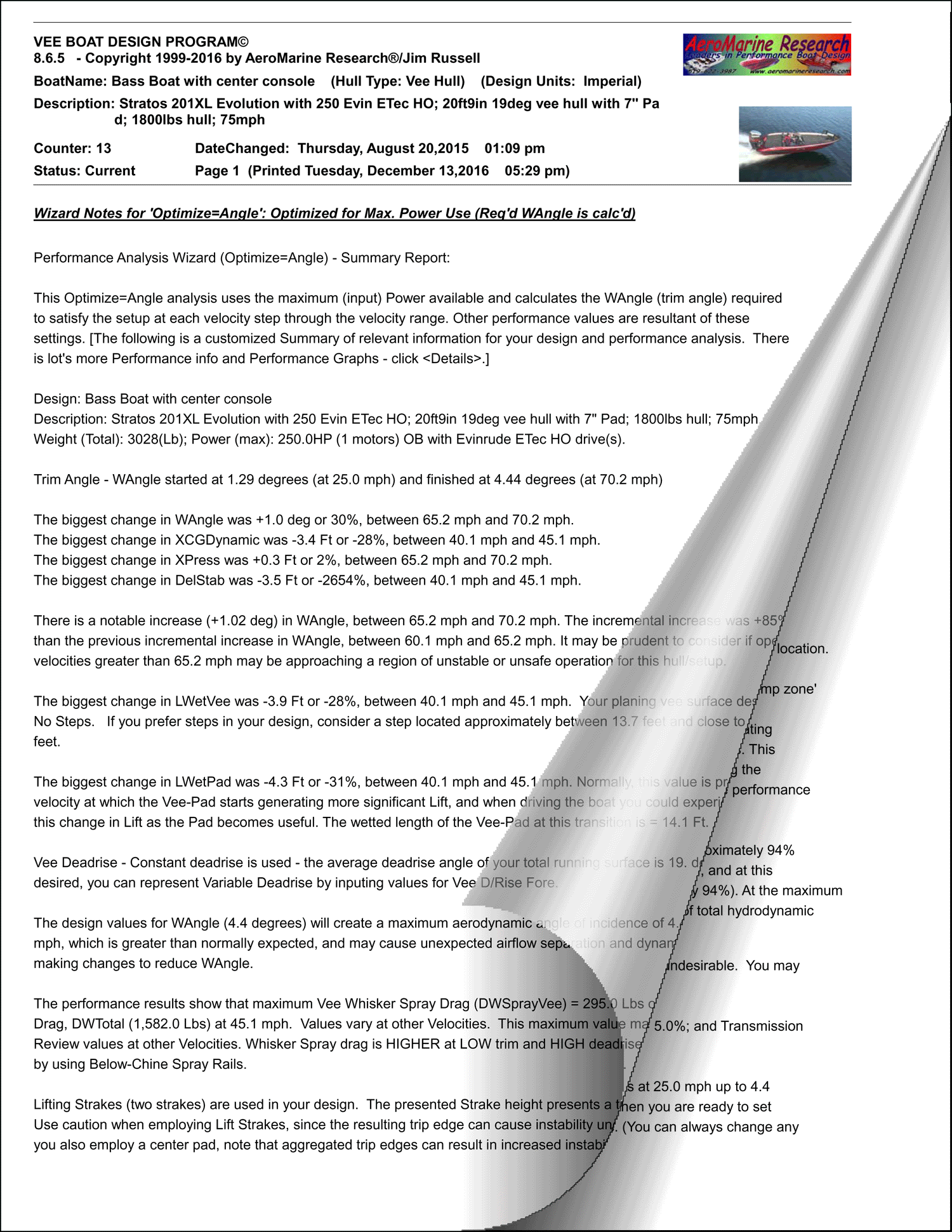
Performance Summary Wizard Report         [see Performance Summary Wizard Report sample]
Performance Summary Wizard Report provides a unique-to-your-design based summary of key performance characteristics, including highlighting of important performance & design features and setup situations that may benefit from consideration or correction.  This is a unique report for your design that can be over 2500+ words of performance wisdom! 

Performance Summary Wizard Report includes custom-narrated analysis commentary for your design on design and performance narrative topics that include:

Tunnel Boat Design Software by AeroMarine Research
Maximum Limiting Velocity Trim Angle Analysis Maximum Practical Velocity Notable Performance Changes & Inflections
Lift Surface Deadrise Aero Angle of Attack Major Lift Component Analysis Major Drag Component Analysis
Dynamic Stability Analysis Hump Transition Analysis Complex Step Design Lifting Surface Performance Analysis
Aerodynamic Lift Analysis Aerodynamic Drag Analysis Spray Rail Analysis Lifting Strake Analysis
Porpoising Analysis Power Efficiency Analysis Design Changes Report Acceleration, Elapsed Time & Distance Travelled Report
Whisker Spray Analysis Force-Moment Analysis Power Efficiency Analysis Propeller Sizing
Wetted Surface Analysis Trim Tab Analysis Motor/Engine Cowl Drag Analysis Comparative Design Analysis  
Cockpit Design Performance Lower Unit Drag Analysis  
 
 
1. Performance Data (Screen #1)       [see Performance Output Screen samples and Performance Graphs samples] 
NAME UNITS DESCRIPTION  
Velocity (mph) CONFIGURED for ANGLE OPTIMIZATION or POWER OPTIMIZATION - velocity is set at Design data input screen by STARTVEL and VELOCITY INCREMENT to determine the range of velocities that predictive performance analysis will be completed for. Solutions for (6) specified velocities will print in columns on the performance analysis screen.

CONFIGURED FOR VELOCITY OPTIMIZATION - velocity is predicted through Optimization program. The velocity that satisfies the specified Angle of Attack and Power Rating is determined.

NOTE: This may be the maximum attainable velocity. There may also be other velocities for which the design produces solutions for the specified input values. The "singular solution" for maximum velocity can be determined by specifying an alternate STARTVEL or varying POWER MAX to examine these alternate modes.
LWetSponson  (ft) Sponson wetted length, limited to maximum length of sponson (LENGTH BOAT).
LWetVee  (ft) Vee surface wetted length, limited to maximum length of vee bottoms (LENGTH BOAT).
SWet  (ft2) Total wetted sponson area, limited to total plan area of both sponsons. Less is better, can be minimized by increased WANGLE or increased PADWIDTH
SWetVee  (ft2) Total wetted vee surfaces area, limited to total plan area of vee surfaces. Less is better, can be minimized by increased WANGLE or increased 1/2 Vee Width
LAero  (lbs.) Total Aerodynamic Lift
DAero  (lbs.) Total Aerodynamic Drag
LWTotal  (lbs.) Total Hydrodynamic Lift
DWTotal  (lbs.) Total Hydrodynamic Drag
DMotor  (lbs.) Total drag of motor appendages , includes motor spray drag (if applicable) and multi-engine interference drag (if applicable).
DCockpit  (lbs.) Total drag of cockpit/cowl, including cavity drag (if applicable)
DTotal  (lbs.) Total Combined Drag, sum of all other drags, required to be balanced by available power (POWER MAX).
WtTotal  (lbs.) Total Combined Weight of Boat, Driver, Motor, Fuel and all miscellaneous hardware.
XCGStat (ft) Location of Static Centre of Gravity (dead balance of boat), referenced fore (+) of the
XCFDynam  (ft) Location of Dynamic C of G, center of balanced moment of all forces while hull is under specified running conditions, referenced fore (+) of the transom location. This will bedifferent for each operating velocity or condition.

[HINT : To maximize stability at operating velocity, XCFDynam should be as close toXCGStat as possible, and XCFDynam should be ahead of the Aerodynamic Center (XPress).Location of weight (e.g. LENGTH DRIVER, LENGTH FUEL) and location of forces (WINGCHORD, LENGTH BOAT) can be adjusted to optimize desired performance.

[NOTE: See also, XCFDynamic Analysis , and Example Analysis of XCFDynamic & XCGStatic]
WAngle  (degrees) CONFIGURED for VELOCITY OPTIMIZATION or POWER OPTIMIZATION - the specified Angle of Attack (Trim Angle) used for predictive performance analysis. Referenced as angle between water surface and sponson bottoms.

CONFIGURED FOR ANGLE OPTIMIZATION - the calculated Angle of Attack (Trim Angle)predicted through Optimization program, based on defined VELOCITY inputs.
XPorpoise  (Ratio:1) a) If XPorpoise is GREATER THAN 1.0 - When your hull is in the "stable planing range", the hull is less likely to experience porpoising. This is a good feature, and your hull will be lesssusceptible to porpoising while operating in this range.

b) If XPorpoise is LESS THAN 1.0 - When your hull is in the "Porpoise instability regime", itis susceptible to porpoising. If porpoising is a performance concern, this is a risk region ofoperation.
PReqd  (HP) Calculated POWER REQUIRED, as predicted through iterative Optimization program , to meet specified VELOCITY or ANGLE requirements.

For VELOCITY and ANGLE Optimization , solutions are reached and are displayed when thecalculated Power Required meets the specified maximum power (POWER MAX) within thetolerance range specified by ACCURACY DEF and at the specified VELOCITY or ANGLEvalues.

For POWER Optimization, solutions are reached and are displayed when the minimumpower required to meet the specified trim angle (WANGLE) at the specified VELOCITY.
Time  (sec) Estimated ELAPSED TIME to accelerate using FULL POWER from one VELOCITY to the next.This is an approximated calculation, but very useful in performance prediction and designcomparisons.
Accell'n  (fps/ sec) Estimated average ACCELERATION rate using FULL POWER from one VELOCITY to thenext. This is a tremendously powerful analysis tool, to evaluate the NET impact that designchanges or differences can/will have on real-life performance characteristics. This is anapproximated calculation, but very useful in performance prediction and designcomparisons.
Distance  (ft) Estimated (cumulative) DISTANCE TRAVELED during acceleration from one VELOCITY tothe next, based on user specified trim angles (WAngle). This is an approximated calculation, but very useful in performance prediction and design comparisons.
 
  back to top of page  
  2. Perf 2 Data (Screen #2)      [see Performance Output Screen samples and Performance Graphs samples]   
NAME UNITS DESCRIPTION 
LWSponson  (lbs.) Total Hydrodynamic (water) Lift from Sponson pad running surfaces.
LWVee  (lbs.) Total Hydrodynamic (water) Lift from Vee planing surfaces.
DWSponson  (lbs.) Total Hydrodynamic (water) Drag from Sponson pad lifting running surfaces.
DWVee  (lbs.) Total Hydrodynamic (water) Drag from Vee planing surfaces.
LWPod (lbs.) Total Hydrodynamic (water) Lift from Center Pod surfaces, when exists (Tunnel hull).
LWPad  (lbs.) Total Hydrodynamic (water) Lift from Center Pad surfaces, when exists (Vee hull).
DWPod (lbs.) Total Hydrodynamic (water) Drag from Center Pod surface, when exists (Tunnel hull) .
DWPad  (lbs.) Total Hydrodynamic (water) Drag from Center Pad surface, when exists (Vee hull).
DWSpraySpon  (lbs.) Drag contributed from Whisker Spray drag from Sponson surfaces
DWSprayVee (lbs.) Drag contributed from Whisker Spray drag from Vee planning surfaces.
DCowlMotor (lbs.) Aerodynamic drag contribution from exposed outboard motor cowling
ARPod  (-) Effective Aspect Ratio of Center Pod lifting surfaces, when exists. Useful for evaluatinglifting efficiency of running surfaces.
ARPad  (-) Effective Aspect Ratio of Vee-Pad lifting surfaces, when exists. Useful for evaluating liftingefficiency of running surfaces.
ARSponson  (-) Effective Aspect Ratio of Sponson lifting surfaces (Tunnel hull). Useful for evaluatinglifting efficiency of running surfaces (e.g.; steps)
ARVee  (-) Effective Aspect Ratio of Vee lifting surfaces (Vee Hull). Useful for evaluating liftingefficiency of running surfaces (e.g.; steps)
L/DSponson  (-) Lift/Drag Ratio of Sponson surfaces
L/DVee (-) Lift/Drag Ratio of Vee hull surfaces
L/DPod (-) Lift/Drag Ratio of CenterPod (Tunnel hull)
L/DPad (-) Lift/Drag Ratio of CenterPad (Vee-Pad hull)
L/DAero  (-) Lift/Drag Ratio of Aerodynamic (air) surfaces
XPress  (ft) location of Center of Aerodynamic Pressure, for aerofoil (Tunnel wing). XPress willchange, influenced by aerofoil shape (configuration) and Angle-of-Attack. Referenced fore(+) of the transom location.
Force-Moment  (lb-ft) Net moment of all dynamic forces acting on hull, about XCGStatic. Positive value meansBOW UP tendancy, Negative value means BOW DOWN tendancy. Lower values are safer.
 
  back to top of page  
  3. Coefficient Data (Screen #3)         [see Performance Output Screen samples and Performance Graphs samples] 
NAME UNITS DESCRIPTION
CLA  (-) Coefficient of Aerodynamic (air) Lift
CDA  (-) Coefficient of Aerodynamic (air) Drag
CLW (-) Coefficient of Hydrodynamic (water) Lift
CDW  (-) Coefficient of Hydrodynamic (water) Drag
CLWSponson (-) Coefficient of Hydrodynamic (water) Lift for Sponson pad running surfaces
CLWVee  (-) Coefficient of Hydrodynamic (water) Lift for Vee planing surfaces
CLWPod  (-) Coefficient of Hydrodynamic (water) Lift from Center Pod surfaces, when exists (Tunnel hull).
CLWPad  (-) Coefficient of Hydrodynamic (water) Lift from Center Pad surfaces, when exists (Vee hull).
CDCowl (-) Coefficient of Aerodynamic (air) Drag for Cowling(s) or Enclosed Capsule (Safety Cell)
CDMotor  (-) Coefficient of Drag for Motor appendages
CDWSpon (-)  Coefficient of hydrodynamic drag for Sponson surfaces.
CDWVee (-) Coefficient of hydrodynamic drag for Vee planning surfaces.
CDWPod  (-) Coefficient of Hydrodynamic (water) Drag from Center Pod surfaces, when exists (Tunnelhull).
CDWPad (-) Coefficient of Hydrodynamic (water) Drag from Center Pad surfaces, when exists (Veehull).
XCGDiff  (ft) Difference between Dynamic Stability location centre of balanced moment of all forces(XCFDynamic), and the static Centre of Gravity location (XCGStat). Very helpful forevaluating overall relative stability. Dynamic Stability is BETTER when absolute value(either '+' or '-') of XCGDiff is smaller (closer to zero).[NOTE: See also, XCFDynamic Analysis , and Example Analysis of XCFDynamic & XCGStatic]
DelStab (ft) Difference between Dynamic Stability (XCFDynam) and the Center of Pressure (XPress), helpful for evaluating relative aerodynamic stability. Should be Positive for stable flight.
YCG  (ft)  Calculated height of C of G. Referenced (+) from water surface. Lower is better.
 
  back to top of page  
  4. Misc Data (Screen #4)      [see Performance Output Screen samples and Performance Graphs samples]   
 
NAME UNITS DESCRIPTION
LWetSponson  (ft) Sponson wetted length, limited to maximum length of sponson (LENGTH BOAT).
LWetVee  (ft) Vee surface wetted length, limited to maximum length of vee bottoms (LENGTH BOAT).
LWetStep2  (ft) Wetted length at/fore of 2nd Step. (When value = 0 then 2nd step is unwetted).
LWetStep1  (ft) Wetted length at/fore of 1st Step. (When value = 0 then 1st step is unwetted).
LWetAftStep  (ft) Wetted length AFT of 1st Step
LWetPod  (ft) CenterPod Lifting surface wetted length (Tunnel hull). Limited to maximum length of CenterPod.
LWetPad (ft) Vee-Pad wetted length (Vee hull). Limited to maximum length of Vee-Pad.
SWet (ft2) Total wetted surfaces area, limited to total plan area of sponsons (vee) and centerpod (vee-pad) . Less is better, can be minimized by increased WANGLE or increased PADWIDTH
SWetSponson  (ft2) Wetted surface area of Sponson lifting surfaces (Tunnel hull)
SWetVee  (ft2) Wetted surface area of Vee hull lifting surfaces (Vee hull)
SWetPod (ft2) Wetted surface area of CenterPod (Tunnel hull)
SWetPad (ft2) Wetted surface area of CenterPad (Vee-Pad hull)
bPlaningSpon  (-) Wetted width of both SPONSON surfaces (combined width). When value = 0 then both SPONSON surfaces are unwetted. (Tunnel hull)
bPlaningVee (-) Wetted width of full Vee surfaces (combined both Vee 1/2 widths) . When value = 0 then Vee surfaces are unwetted. (Vee hull).
bPlaningPod  (ft) Wetted width of CENTER-POD surfaces. When value = 0 then CENTER-POD surfaces are nwetted. (Tunnel hull)
bPlaningPad  (ft) Wetted width of VEE-PAD surfaces. When value = 0 then CENTER-POD surfaces are unwetted. (Vee-Pad hull)
CPSponson  (ft) Location of Center of Lift for SPONSON surfaces, including steps. (referenced fore (+) of the transom location.)
CPVee  (ft) Location of Center of Lift for VEE surfaces, including steps. (referenced fore (+) of the transom location.)
CPPod  (ft)  Location of Center of Lift for CENTER-POD surfaces (referenced fore (+) of the transom location.)
CPPad (ft) Location of Center of Lift for VEE-PAD surfaces (referenced fore (+) of the transom location.)
DWSpraySpon (lb) Coefficient of drag for Whisker Spray drag from Sponson surfaces
DWSprayVee (lb) Coefficient of drag for Whisker Spray drag from Vee planning surfaces.
DWSprayPod (lb) Coefficient of drag for Whisker Spray drag from CenterPod surface OR from Vee-Pad surfaces.
DWSprayPad  (lb) Coefficient of drag for Whisker Spray drag from Vee-Pad surfaces.
LWTrimTabs (lb) Hydrodynamic (water) Lift for Trim Tabs engaged
CLWTrimTabs  (-) Coefficient of Drag for Trim Tabs
DWTrimTabs  (lb) Hydrodynamic (water) Drag for Trim Tabs engaged
WAngleTrimTabs  (deg) Deflection angle of Trim Tabs engaged.
ARTrimTabs  (ft/ft) Effective Aspect Ratio of Trim Tabs
PercentPodLift  (%) Percent (%) of total hydrodynamic Lift contributed by Center-Pod (Tunnel hull)
PercentPadLift  (%) Percent (%) of total hydrodynamic Lift contributed by Vee-Pad (Vee-Pad hull)
PercentSponsonLift  (%) Percent (%) of total hydrodynamic Lift contributed by Sponson surfaces (Tunnel hull)
PercentVeeLift  (%) Percent (%) of total hydrodynamic Lift contributed by Vee surfaces (Vee Pad hull)
 
  back to top of page  

jim2.jpg secrets_of_tunnel_boat_desi.gif

about Jim Russell

"Secrets of Tunnel Boat Design - Second Edition"
book
 "Secrets of Propeller Design" book

"TBDP Version 8" Software "VBDP Version 8" Software "PropWorks2" software

Order with your Shopping Cart
Special pricing updated September 29, 2024
Contact us at:
AeroMarine Research®
67 Highland Crescent, Cambridge, ON, Canada, N1S1M1
Tel: 519-240-7959

©Copyright by AeroMarine Research and Jim Russell, 1999, all rights reserved.
Material from this website may be not copied or used or redistributed, in whole or in part, without specific written consent of Jim Russell or AeroMarine Research®.