|
Advanced analysis of the changing
hydrodynamic and aerodynamic forces acting on tunnel hulls and vee
hulls gives highly accurate dynamic stability, performance predictions &
optimization.
TBDP/VBDP Longitudinal Stability
Analysis predicts onset of insabilities including nose-dive
(stuffing), bow-steer, bow-trip, bow-raise, high bow lift or
blow-over, and more.
How To Evaluate:
To
maximize hull stability:
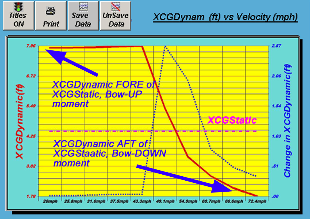
1) 'XCFDynamic' should be as close to
XCGSTAT as possible [see Graph#12]
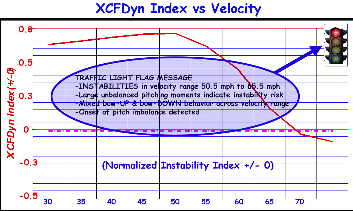
2) 'LongStab Index' (CMCG) should be as
close to zero (either '+' or '-') as possible [see Graph #70]
3) d(CMCG,
V) - change in 'LongStab Index' should be small [see
'Performance Results Wizard' (Longitudinal Stability)]
4) Persistence of (above)
indicators across velocity steps
5) BowUP/BowDOWN Force
Moments
6) combinations of these
conditions.
NOTE: Stability indicator results are
not ONLY value-based, see the 'trend-based' ASSESSMENT provided
in 'Performance Summary Report' and the 'TRAFFIC LIGHT' symbol
on this graph. CLICK on 'TRAFFIC LIGHT' symbol for
DETAILED
STABILITY REPORT.
Read on for explanation
of these analytical indicators...
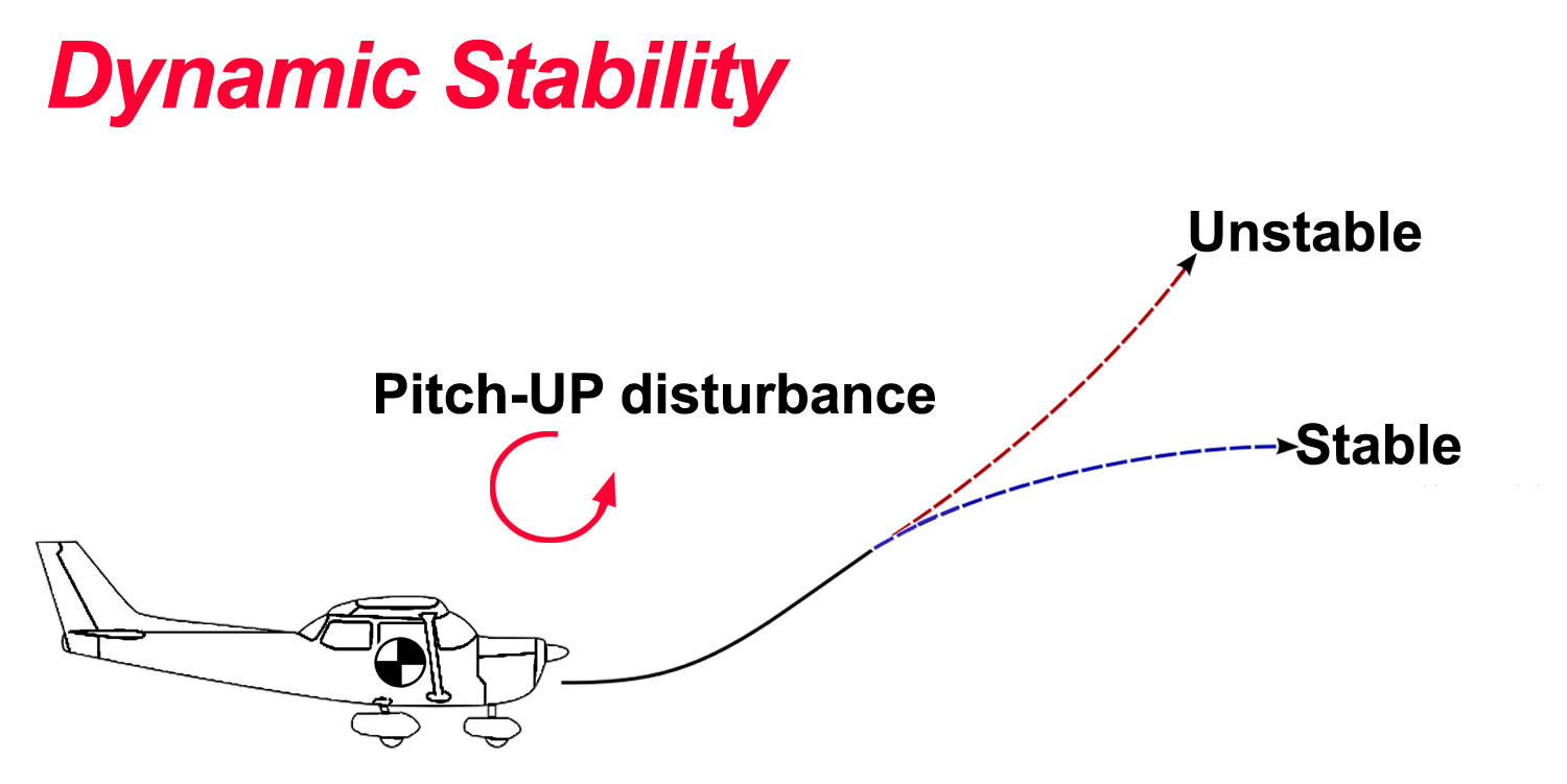
Pitch Stability
Beyond Trim Equilibrium
Traditional trim analysis
determines the equilibrium trim angle of a planing hull at each
speed. While necessary, equilibrium trim alone does not indicate
whether the hull will naturally resist pitch disturbances or
whether small changes in speed, trim, or loading may lead to
persistent imbalance or instability.
The Dynamic Longitudinal
Stability analysis developed by AeroMarine Research evaluates
the restoring quality of the longitudinal force balance across
speed. It identifies operating regions where pitch stability
margins are strong, weak, or changing, providing designers with
insight that conventional trim solvers do not supply.
Making it Easy:
While stability analysis is complex, TBDP©/VBDP© presents a
reporting format that makes Results and Recommendations easy
to understand...
TBDP©/VBDP© presents a full
range of reporting information that makes the results and
recommendations easy to understand.
For each of the Stability
measures, the software does ALL the work behind the scenes, and
gives both DETAILS and also gives the 'GOOD/NO GOOD' summary of
all considerations. [Check out
'Easy Results View' here]
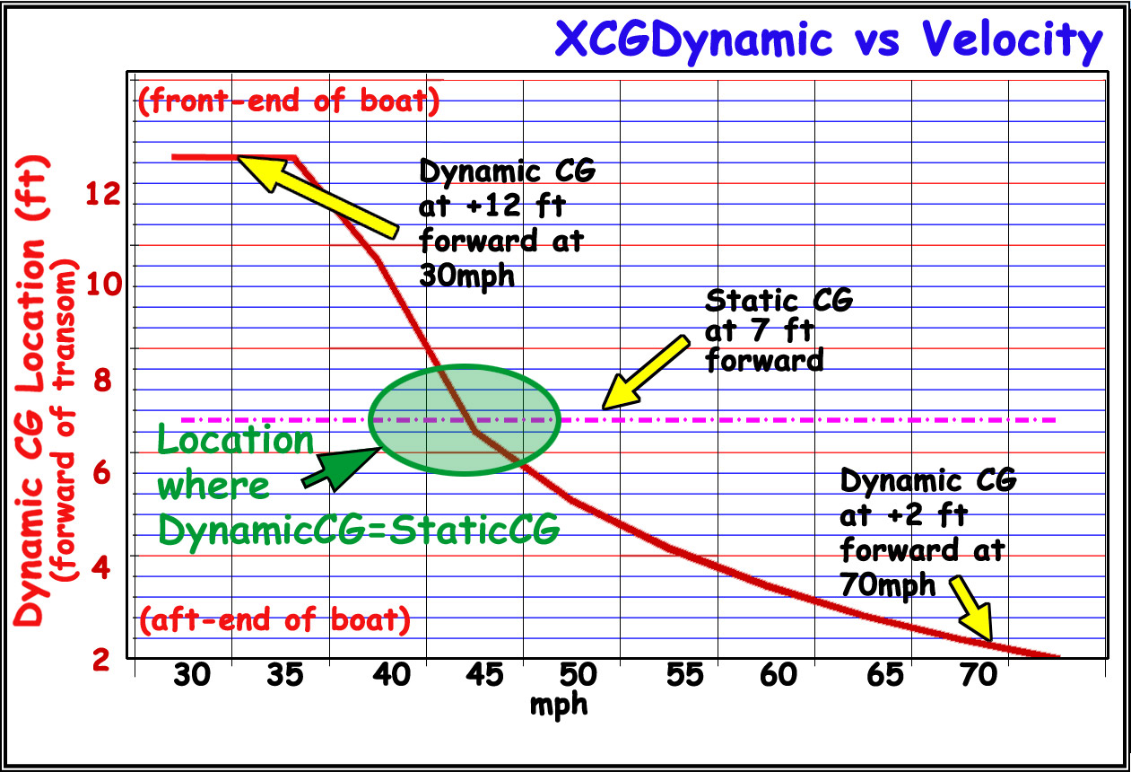
Why Static hull
'balance' doesn't help...
The 'Static CG' of a hull is the location of balance of the hull,
appendage and payload deadweights
while boat is at rest.
But this is a small part of the important balance of a performance
hull - particularly since the performance boat usually operates
at velocities greater than zero! [check
out article here]
The combined center of ALL the lift forces
and all the drag forces (sponsons, center-pod, vee surfaces, center-pad,
aerodynamic surfaces, lower unit, etc.) while a boat is under way,
is called the 'Dynamic Center of Forces' or 'xCFDynamic'
centroid. The 'xCFDynamic' location changes throughout the operating velocity range and
is the most important design measure to consider when 'balancing'
a performance boat.
Some situations that can evolve as
triggered by dynamic instablity include…
-
Porpoising
-
Blowover
-
Barrel Roll
-
Nose-Dive ('Stuff')
-
Airborne
Note analysis methods apply
SIMILARLY to
all styles, sizes, configurations of hulls, and for all weights,
power and velocities - different hulls - same analysis.
How it Works...
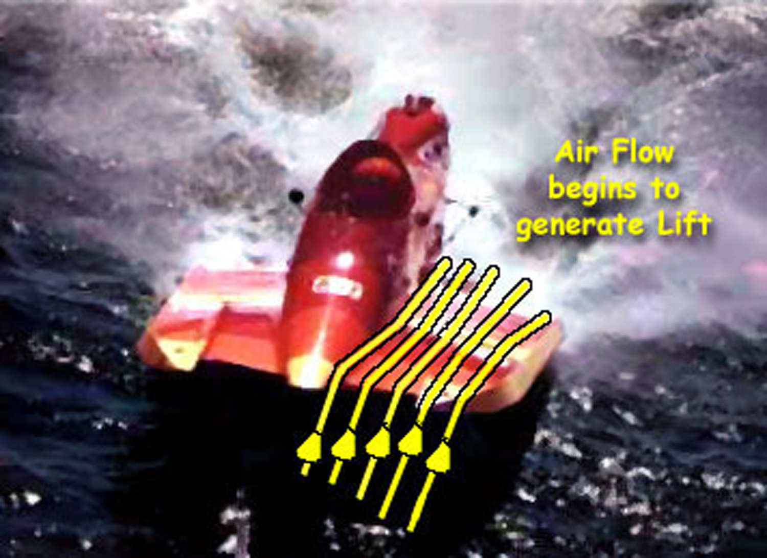
Lift = Weight = Performance - All boats must generate enough
lift to balance the weight of the hull. Performance tunnel and vee
hulls generate lift by hydrodynamic 'planing' surfaces and aerodynamic
surfaces. As a boat goes faster it needs less wetted surface to
generate it's required Lift – but that Lift is always equal
to the weight of the boat – and the Lift always comes with
a certain amount of drag.
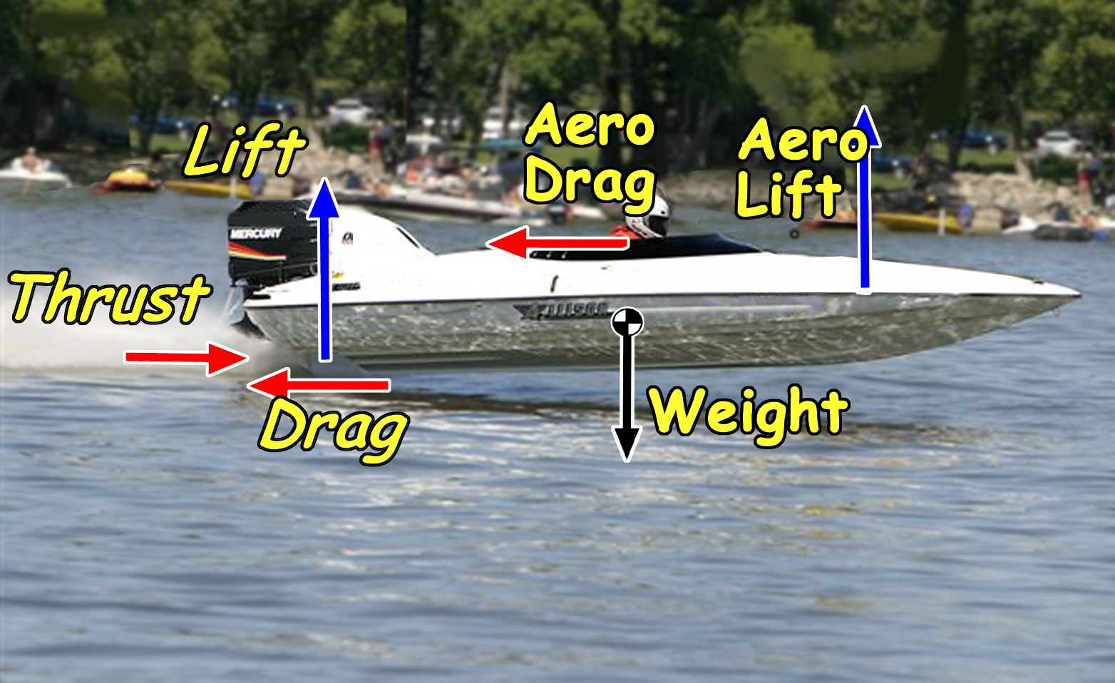
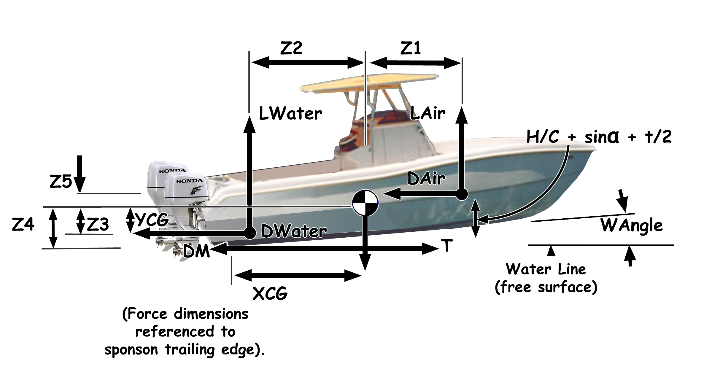
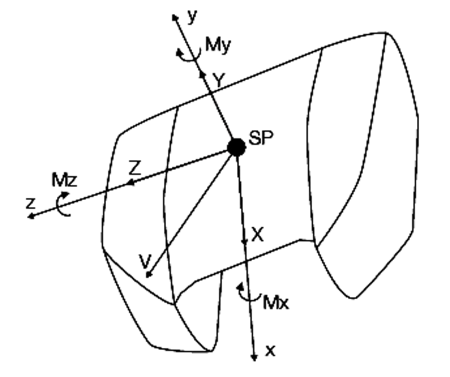
Core Physical Principle - At any operating speed, a planing hull is acted upon by multiple
longitudinal forces, each applied at a different longitudinal
location:
- Hydrodynamic planing lift and drag
- Propulsive thrust‑line forces
- Lower‑unit hydrodynamic forces
- Aerodynamic lift and drag (when applicable)
As
speed changes, both the magnitude and the location of these
forces change. Stability depends not only on their sum, but on
where their combined line of action lies relative to the
vessel’s center of gravity (CG).
Tunnel hulls see a unique balance between aerodynamic Lift generated by the
deck and or tunnel configuration, and the hydrodynamic Lift
generated by the sponson surfaces on the water.
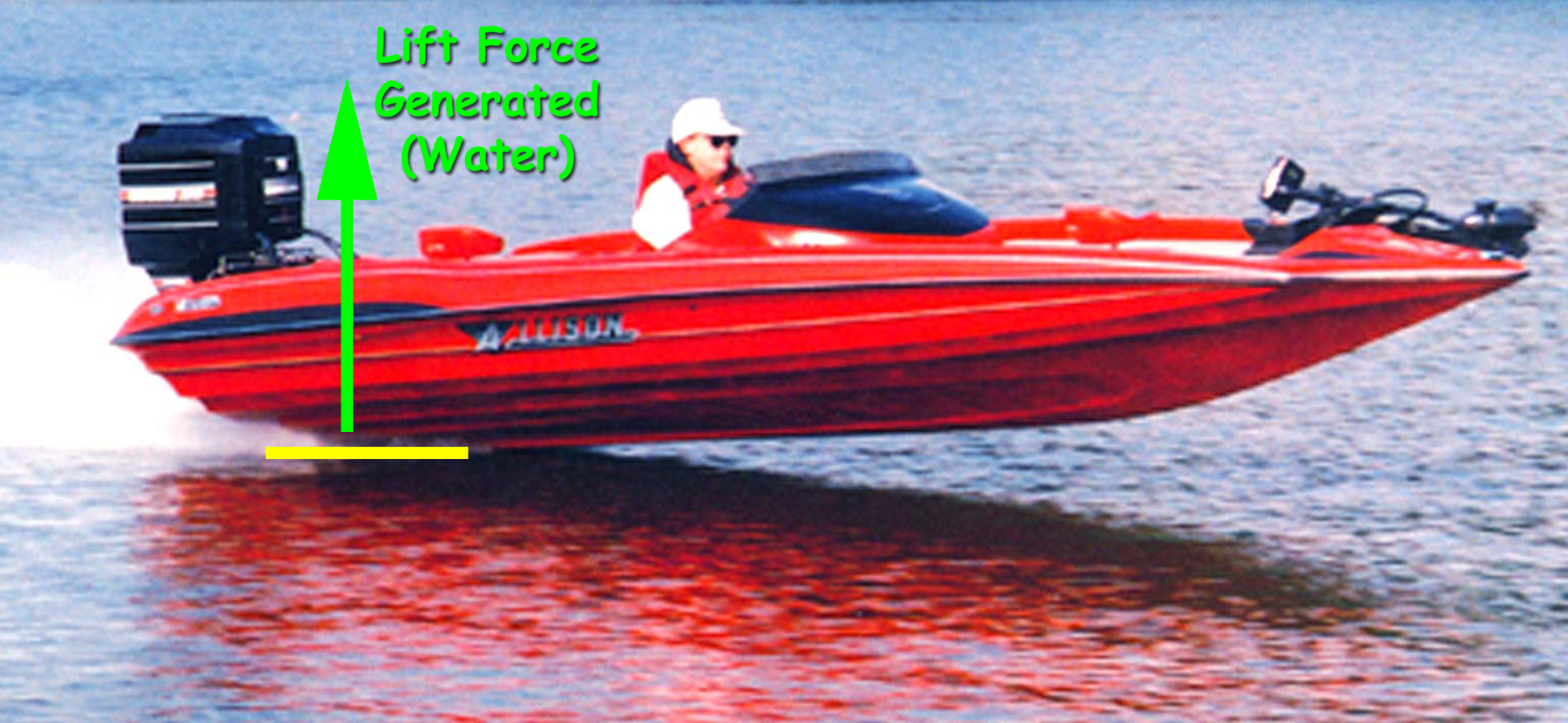
Vee hulls (and Vee-Pad hulls) gain lift from
the balance of lift from planing vee surfaces and/or center-pad
surfaces and also from aerodynamic surfaces.
Hump Zone
The “hump zone” for a tunnel hull represents the speed
at which a more significant amount of Lift changes from sponson
lift to aerodynamic lift.
For Vee hulls the "hump zone"
transition occurs when a more significant amount of Lift changes from vee
surfaces lift to aerodynamic lift and/or vee-pad lift.
This "hump"
or "transition zone" occurs at a different velocity with
each boat and setup. The change in location of the center of
Lift (with increasing velocity) is often quite dramatic and can
initiate the onset of potential
instabilities - like Porpoising or chinewalking.
We have developed a mathematical
method to accurately predict the onset of instability and the
point of the 'Hump Zone Transition".
Net Longitudinal Force Centroid (xCFDynamic)
For each speed, the analysis
computes xCFDynamic, defined as the longitudinal centroid of all
resolved forces acting on the hull:
xCFDynamic = net longitudinal location at which the total force system acts
This quantity moves with speed as
the force balance evolves. The hull’s center of gravity, by
contrast, remains fixed (static). The separation between
XCFDynamic and the CG is the fundamental indicator of
longitudinal pitch stability.
Pitch Stability Index (CMCG)
To evaluate restoring behavior in a
consistent, comparable manner, the force‑centroid offset is
normalized to produce a dimensionless pitching moment indicator:
CMCG = Dimensionless pitching
moment coefficient about the CG
CMCG represents both the direction
and relative strength of the net pitching moment...
The sign and magnitude of CMCG indicate
whether the hull is naturally restoring or sensitive to
disturbances.
|

