|
|
|
 |
|
| Performance Boat design and setup secrets for Recreational tunnels, Offshore Cats, Racing tunnels, Fishing/Utility hulls, Vee and Vee-Pad Hulls, Bass Boats | |
| Home New About Us Free Articles Technical Articles TBPNews Archives FREE Downloads Research Contact Us | |
Testimonials What Others Say
Join
TBPNews Advertise
Links
Search Buy Now 
|
|
| AR© develops advanced analysis techniques for Center-Pod Design | ||
| Get complete article by email request: | Share: | |
| Updated: Dec 21, 2024 | BREAKTHROUGH! | |
|
|
TBDP©/VBDP©
analyzes Lift and Drag contributions, force locations, wetted lengths and
wetted areas to optimize performance and dynamic balance of hulls with
center pod - for ANY hull design configuration, throughout the
entire operating velocity range Center-Pod Analysis - Traditional software and analysis techniques often fail to address the interaction of coincident lifting surfaces, such as sponsons and center pod surfaces. While many design and configuration elements affect the lift affectivity of each individual surface, the contribution from each surface also influences the action of all other surfaces. This interdependence of lifting mechanisms is much more complex to model and analyze.
TBDP©/VBDP© solves this balance effectively and accurately. This capability
allows the user to simulate overall performance and dynamic stability of the
total hull design, and ability to optimize the contributions of each surface.
Center Pod design
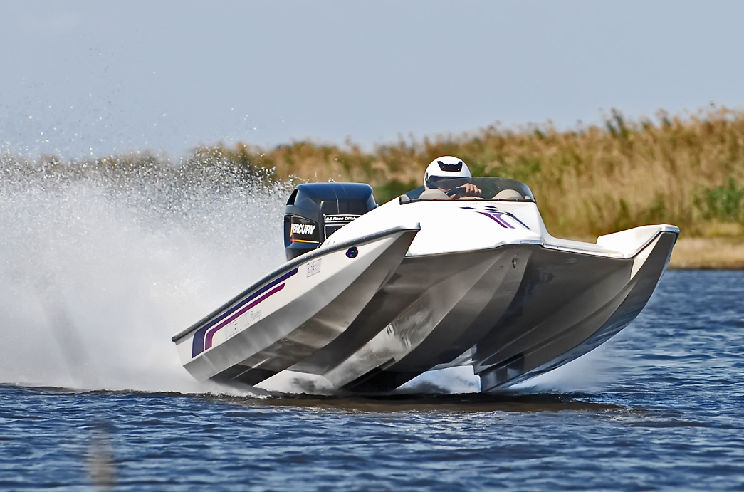
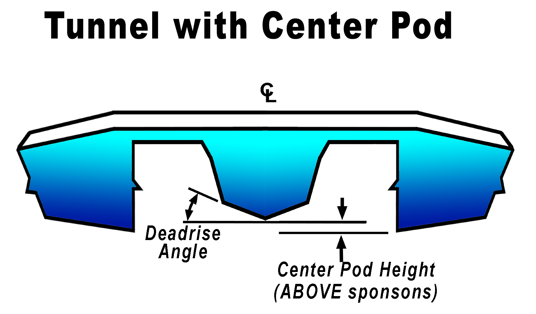
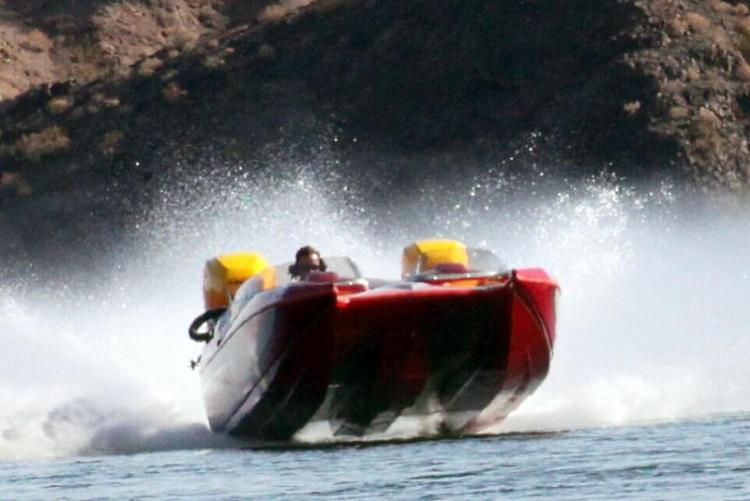
- Many designs of present-day tunnel hulls now sport a center pod, a
centrally located third hull or 'pod' [see Figure 1]. This additional hull
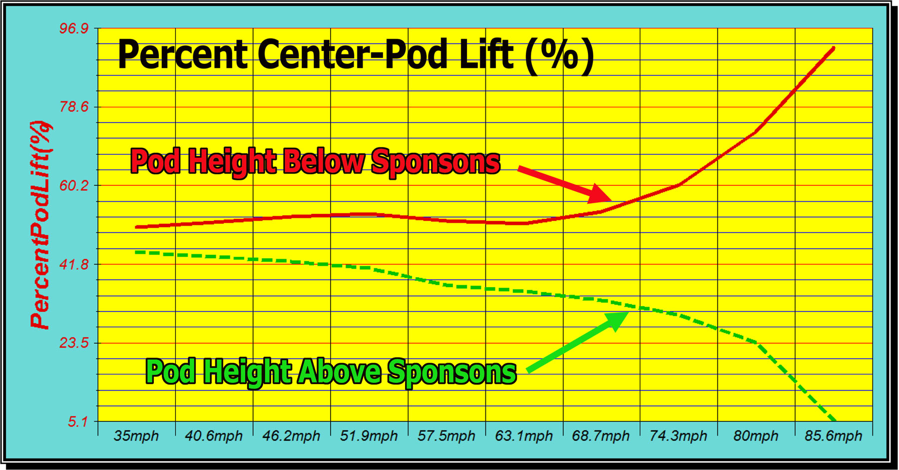
section gives additional lift and is often located higher (or lower) to the
water than the outboard sponsons for diverse lift advantages at early (or
later) velocities. Recreational hulls routinely use a center pod feature; even F1
racing hulls sport a style of center pod for their unique needs. Design Features of
Center Pod can be configured as: With the extra wetted planing surfaces that come from the added center pod, boats can often accelerate faster, particularly if the pod planing surfaces are of very low deadrise. Tunnel hulls designed for 'drag racing' or quick
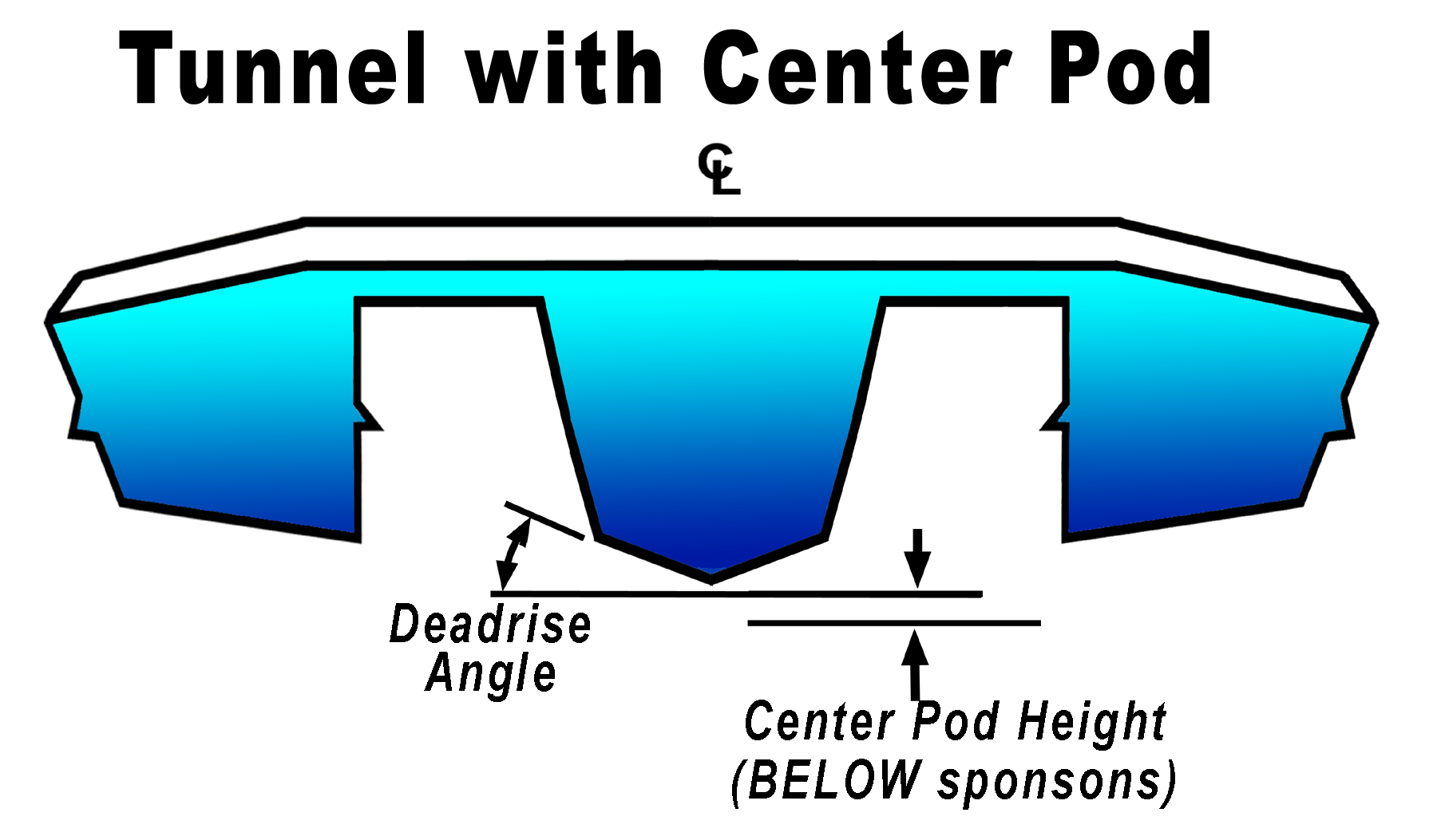
acceleration are sometimes
designed with a deep center pod (below the sponson bottoms) that can improve
low/mid speed acceleration. At top speed a low-deadrise pod is designed to
support the full weight of the boat, with sponson bottoms completely
unwetted for less drag, and the hull tends to behave like a vee hull at very
high speeds. [see Figure 3] For hulls where the ultimate top speed a goal, the center pod will reduce the maximum velocity attainable since the pod degrades aerodynamic lift and adds hydrodynamic drag. A tunnel design with a clean, undisturbed tunnel roof surface, and properly sized sponson surfaces, is always going to be more aerodynamically efficient. So a pure tunnel design (without center pod) is usually the ultimate fast machine. Race hulls often employ a
shallow center pod through the use of a 'built-down mid section'. These came
into practice with the capsule design and is used primarily to reduce the
height of the cockpit section, thereby lowering the CG of the driver and
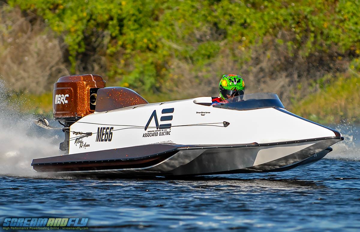
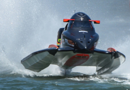
reducing the height of the cockpit or canopy. F1 race tunnel
hulls have 'shallow' center pod that is designed to become un-wetted at top speeds.
[see Figure 5]. The
center structure also strengthens the tunnel span, as these boats can
experience 4+Gs in turns and their tunnels spans can be highly stressed
through the middle of the tunnel due to wide spans and thin sections between
the sponsons. This feature can also improve acceleration through cornering
maneuvers and can improve handling in rough waters. Similarly, pod performance is heavily influenced by the relative pod angle of attack, as compared to the sponson bottom surfaces. Center pod planing surfaces can be designed with a 'Pod Angle' that is the same as sponson bottom surface OR a 'Pod Angle' that is greater than the sponson bottom surface (egg +2 degrees). The latter feature can increase Lift generated by the pod surface due to the greater local 'effective trim angle' (hull trim angle + Pod Angle). Pod surface deadrise can be designed to be different to sponson surface deadrise. Higher Pod deadrise angle can provide wave-breaking benefits and anti-porpoising benefits, while contributing somewhat less Lift. The overall performance result of the center pod addition to a tunnel hull design is a complex one because there are so many hydrodynamic and aerodynamic features working together, generating offsetting efficiencies. It is necessary to analyze the complete hull design in order to determine the overall performance comparison of different center pod configurations for a hull's weight, power and operating conditions. Some boats can benefit from a center-pod while others will not. What works successfully for one hull design and conditions may not benefit another design or operating situation at all. TBDP©/VBDP© software analysis accounts for the use of a center-pod feature (tunnel hull) and also center vee-pad feature (vee hull) and calculates all contributing lifts, drags, force locations, wetted lengths and wetted surface areas, inter-related forces effects, dynamic stability - making performance optimization easy. |
|
|
Research results now included in performance analysis by TBDP©/VBDP© [more about AR's research more about AR's publications and technical articles/papers] |
||
|
© Copyright 2024 by Jim
Russell and AeroMarine Research® - all rights reserved. Material from this website may not be copied or used or redistributed, in whole or in part, without the specific written consent of Jim Russell or AeroMarine Research. |
||
