|

Stepped hull geometry is complex, and
generates better Lift/Drag ratios due to higher Aspect ratio for similar
wetted surfaces.
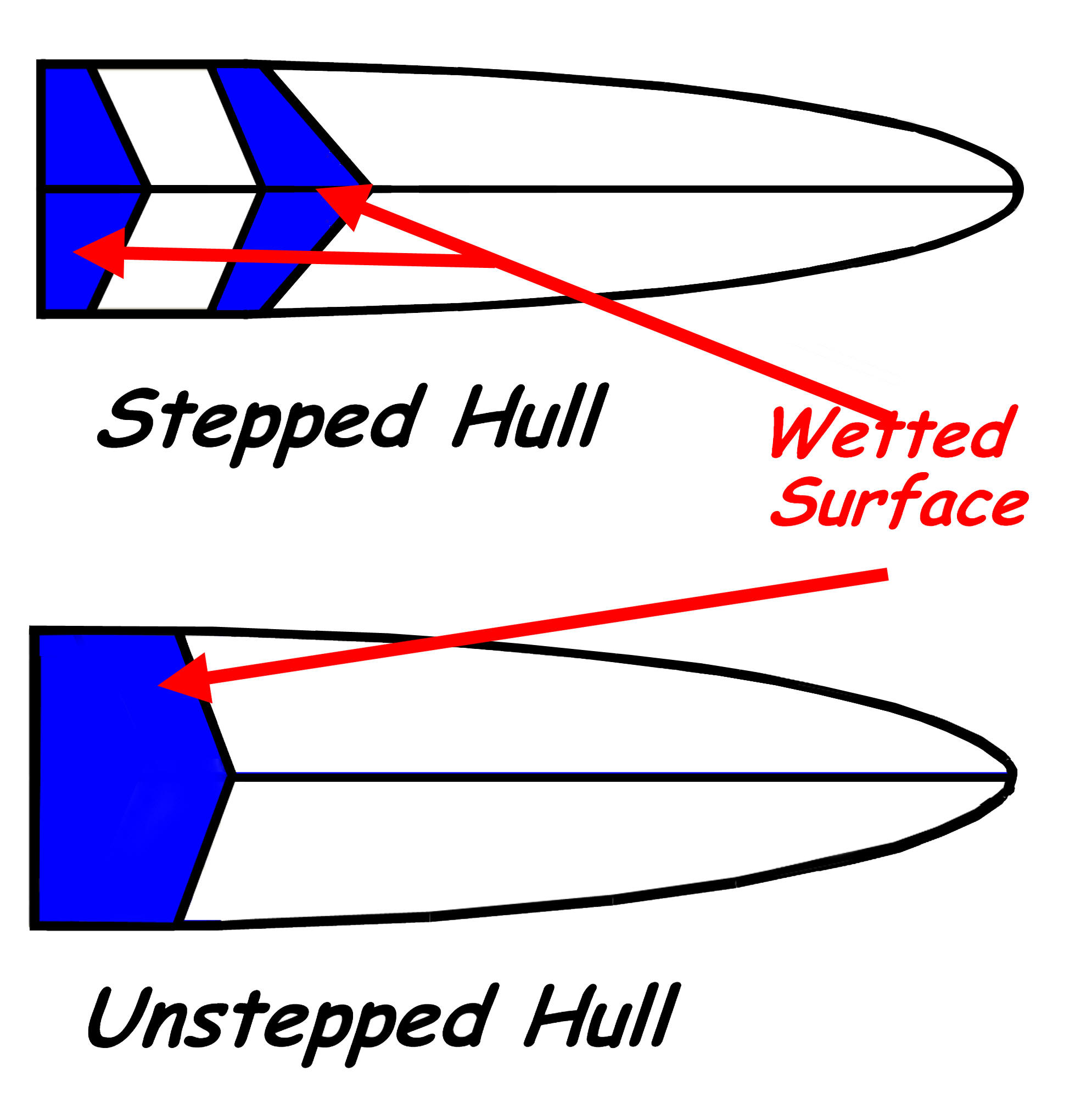
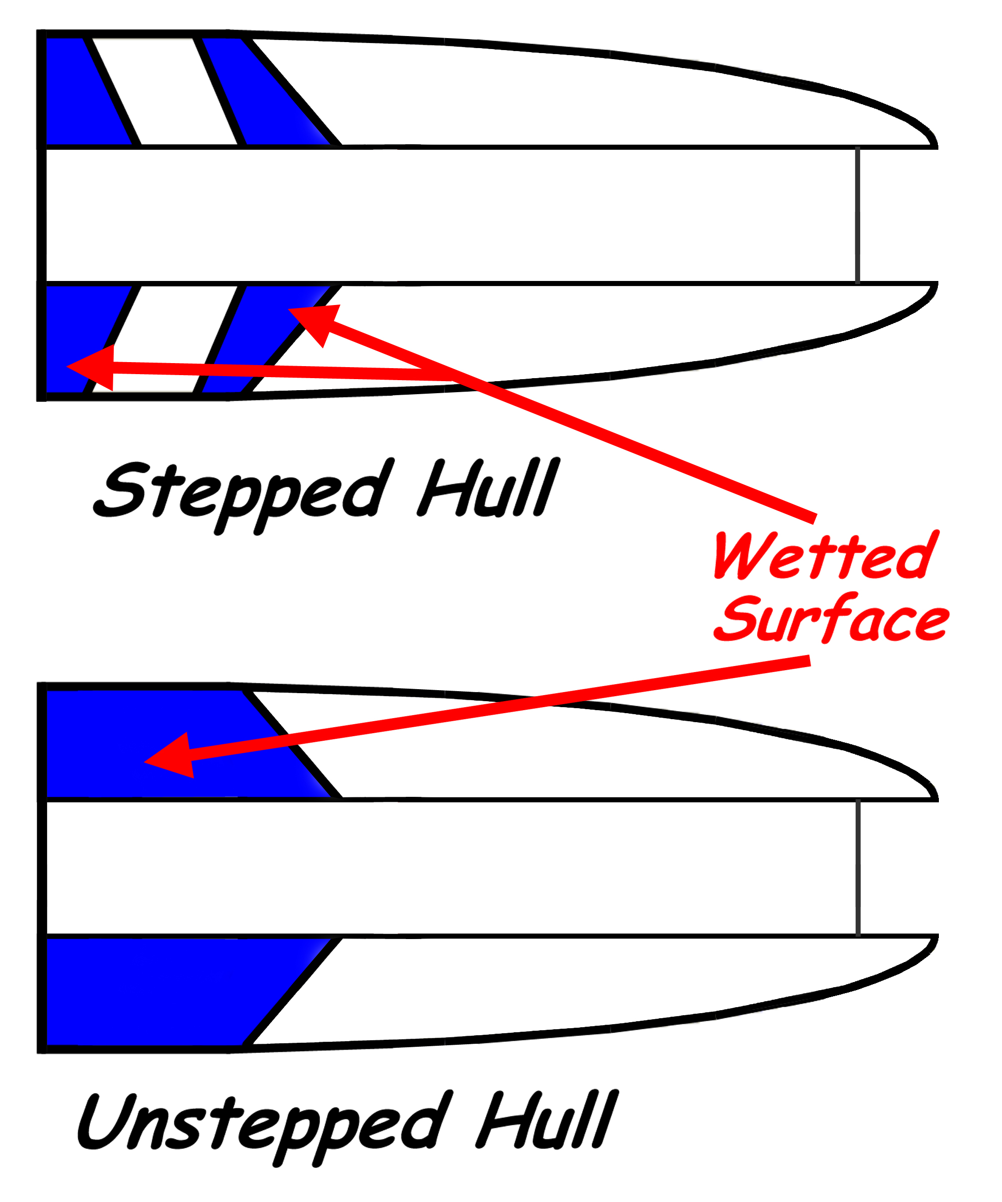
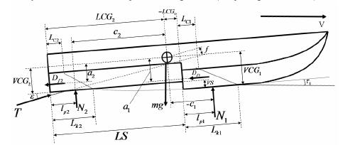
For Vee hulls (left) and Tunnel hulls (right),
Steps can generate required wetted surface with improved
Lift and Drag characteristics.
Stepped hulls operate with a larger effective
angle of attack due to the inherent step angle 'built-in' to the
planing surfaces.
Wetted surfaces of each stepped area have a
controlled location of forces, and usually enhanced Lift efficiency due
to local 'angle of attack' and higher local aspect ratio.
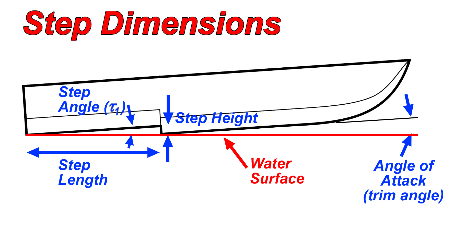
Dimensions of Step configuration are
referenced relative to the 'Water surface'.
Multiple Steps can improve performance through greater velocity range.
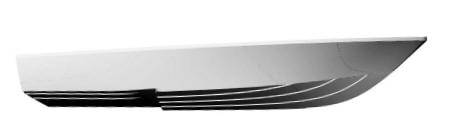
Stepped Vee hull
model.
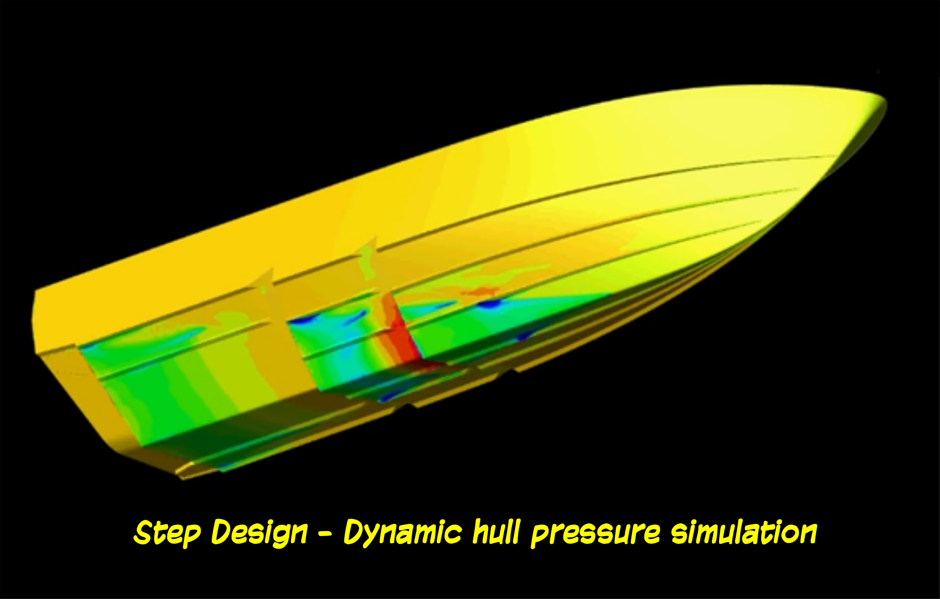
Simulation - Stepped vee
hull pressure distribution

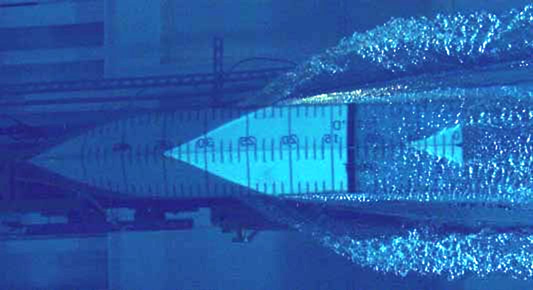
Typical stepped hull wetted surface,
water channel proof testing.
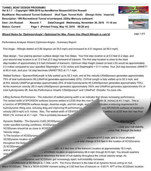
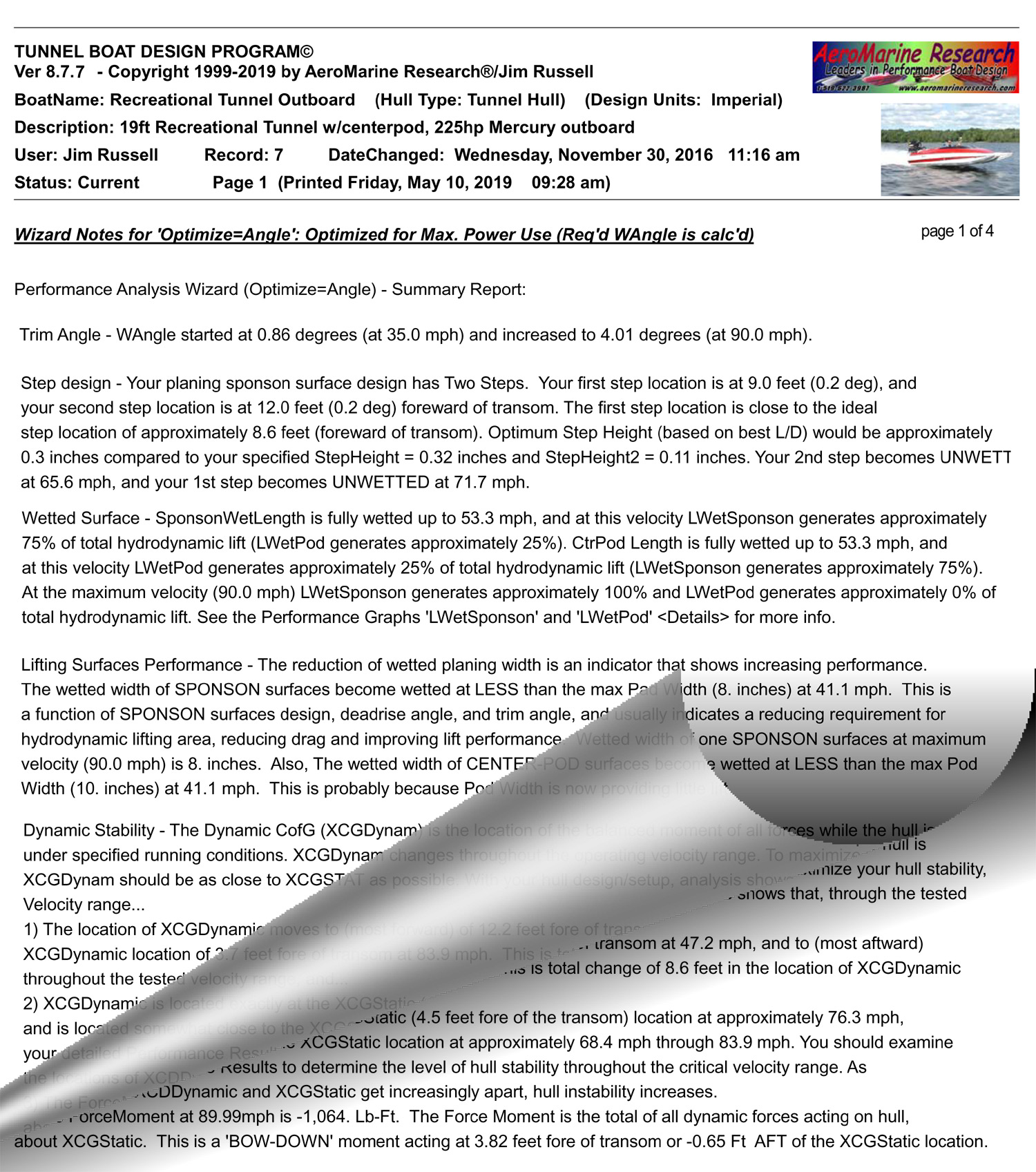
'Steps Analysis' report [excerpt
TBDP/VBDP performance analysis report, pg 1 of 4pgs]. |
|
AR® has developed advanced analysis techniques that accurately calculate
the performance effects of single or multiple steps in
tunnel hulls and
vee
hulls. [See more details on Step design and performance
analysis in 'Secrets
of Tunnel Boat Design - Second Edition' book and 'Tunnel
Boat/Vee Boat Design Program' software.]
Complex Analysis and Results
TBDP©/VBDP© software provides a step analysis
through the full operating velocity range, including trim angle, dynamic
stability, local step loading, changing wetted lengths for each step(s) section,
velocity when each step becomes 'unwetted', location of lift/pressure forces for
each stepped planing surface, total hydrodynamic lift force map, step
angles, even
effects on porpoising. Comparative/optimizing analysis is simple provided
by graphically comparing results of different design
alternatives.
What Steps are NOT...
There is much
information published that inaccurately explain how steps work and
inadequately predict the performance of a stepped hull. For example it's
inaccurate to describe that "Steps introduce air under the boat. The water that runs aft
of a step contains small bubbles, and since aerated water produces less
drag than solid water, stepped hulls are more efficient."
This 'aeration'
example is a common explanation of how steps work, but is really not
proper. if there is 'aerated' water under a step surface, while it's true
that the density of the air/water mixture would be less than water, it is
this same (lower) density that causes all the LIFT that is generated - so
if the density is less, then so is the lift. so less efficient lift means
more wetted surface, and accordingly, not less drag. We've tried to
provide a better, more meaningful technical
explanation of how steps work, and an accurate
analytical representation of step performance.
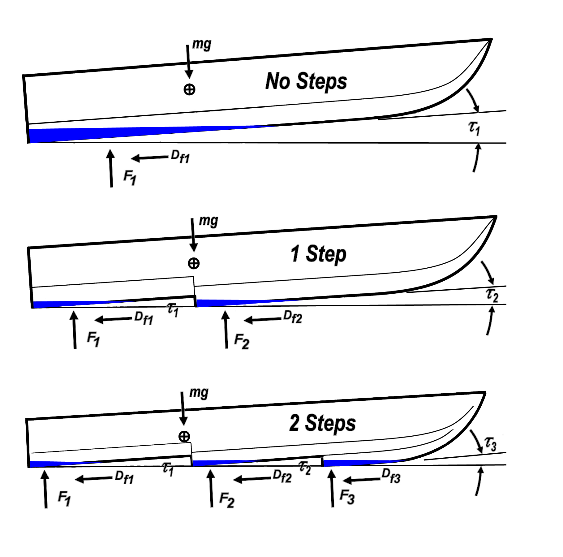
Making a Step Work
A stepped hull can
be visualized as a flat or deadrise bottom with longitudinal "offsets".
When functioning, the area immediately aft of each step is void of water -
an air or air/water mixture. At low speeds, the entire hull bottom
is in the water, but at higher speeds only a portion of each step is wet,
so theoretically we should get less hull drag.
The stepped hull
creates 2 (or more) planing surfaces that helps maintain a constant (trim)
angle of attack for more efficient lifting. The stepped hull has less
bottom surface in contact with the water creating less drag and allows for more
potential speed.
The 'fore' and 'aft' planing surfaces created by the
'step' have two main
advantages...
1) Steps can maintain a constant and near optimum angle of attack
throughout a wider speed range; and,
2) Steps can reduce the amount
of wetted surface that is not near the leading edge (and would otherwise
produce less efficient lift).
Jim Russell applies these advancements in
newest versions of AR®'s TBDP©/VBDP© performance
analysis software. Your design inputs are pretty simple, but the
analysis is complex and the performance results are outstanding!
Step
Design
The design of an effectively performing step will most
always achieve optimum 'benefits' (more than the 'losses') at only one
velocity. A step design is generally only optimized for a single (trim) angle
of attack at a unique velocity, and a single center of gravity (LCofG). This is why it is
complicated to find a step design that can 'help' the performance
throughout the entire speed range of a performance boat.
Consideration of step performance at all operating velocities is
important.
The
planing surfaces of the stepped hulls operate with a larger effective
angle of attack due to the inherent 'Step Angle' that is 'built-in' to the
planing surfaces. Even though the hull 'Trim' angle is often less, the
higher total angle of attack can generate improved CLW (more efficient
Lift). The result is a lesser (total) wetted surface requirement and less
Drag.
The location of Total LW (all planing surfaces hydrodynamic lift) is
normally located further forward in a stepped hull design, as compared to
a non-stepped hull. This can sometimes have a desirable effect on
XCFDynamic (Dynamic Center of Forces).
Here's How It Works
The
hydrodynamic Lift generated by planing surfaces is influenced, in part, by
the surface area, aspect ratio, and trim angle of the wetted surface(s).
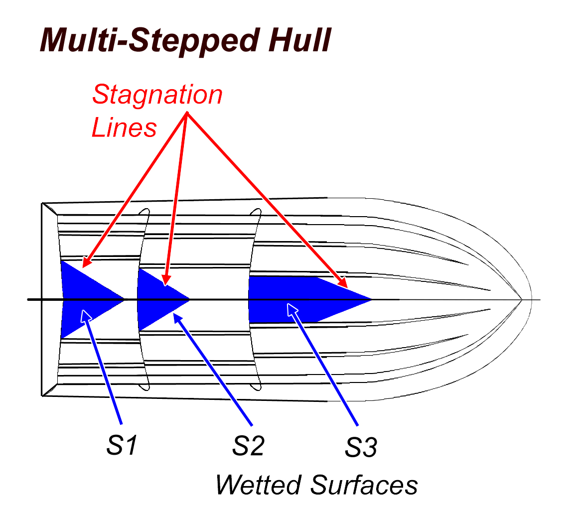
In the case of a stepped hull design (say 2 steps), there can be 3
separated wetted surfaces. If effectively designed, these 3 separate
lifting surfaces can be more efficient than the single surface that a
non-stepped hull could deliver.
The
step design imposes a set angle of attack for the planing surface area aft
of the step. This 'step angle' incrementally increases the total
'trim angle' that the planing surfaces see (hull trim angle + step angle =
total 'planing trim angle'). Higher trim angle generates more lift.
At the same time, the 'Aspect Ratio'
(width/length ratio of the planing surface) for each of the 3 lifting
surfaces of the 2-step hull are greater and so contribute to more
efficient lift (more lift, less drag) than the shape of a longer, single
(non-stepped) planing surface.
Finally, the imposed 'step angle' helps
maintain a minimum angle of attack for the surfaces that, if properly
designed, can optimize the lifting efficiency (L/D) of each surface. Any change in trim angle affects each of the 3 planing surfaces - which
also changes the wetted surface and AR too, and thus affects the Lift &
Drag generated by each of the 3 surfaces. So the performance
analysis of step design is quite complex. Overall, however, there
are benefits of the application of steps to a hull design. [TBDP©/VBDP©
software does all of the engineering calculations and performance analysis to optimize effective multi-step design].
Contributors to Step
Design/Performance
Hydrodynamic forces and effective lifting
surface shapes, areas and local attack angles at each individual
step surface must be calculated, based on key contributors and local
conditions throughout the entire operating velocity range:
- Step Location
- Step Length
- Step Height
- Step Angle (Τ)
- Surface Deadrise angle (β) at local step
- Trim Angle (α) at local step
- Planing surface configuration forward of step
Step Performance can be determined based
on:
-
Lift force (loading) at each local step
-
Drag at each local step
-
Whisker spray drag at each local step
-
Unwetted void length aft of forward step
-
Wetted width (bWidth) at local
step
-
Wetted Length (LWetStep)
-
Centre of Pressure of local step lifting
force
-
Hull trim angle
(αh)
Step forces can influence hull performance as:
- Total Wetted surface
- Total Wetted length
- Centre of Dynamic Lift wrt CG
- Effective trim angle (αe)
- Porpoising onset velocity
- Effective Step(s) CL, CD, CP
- Effective Aspect Ratio (ARstep)
- Unwetted step surface(s) Velocity (VLStep=0)
- Dynamic Stability
- Dynamic Centre of Forces (XCFDynamic)
[Note: All of these influencing
dimensions, forces and factors are calculated by TBDP©/VBDP©
software for complete performance analysis of multi-step design].
Issues with Steps
The most significant issue with step design is the engineering challenge
of properly locating an efficient step on the hull. The length of planing
surface behind the step (i.e.: the location of the step) and depth of the
step have an impact on the performance of the setup. Designing the step
incorrectly can actually decrease performance. The issue of multiple steps
makes the challenge even trickier. So, it is critical to have a
defined understanding of how much
effective lift that a stepped planing surface will generate and
at what (longitudinal) location each
stepped planing surface will be acting.
Some designers stay away from
including steps in designs because of degradation in performance at low
and moderate speed range. At lower speeds the steps are entirely
immersed, so each step actually adds drag to the hull. At moderate speeds
during the transition to full planing, air must get back behind the steps
or the boat will suffer the penalty of continuing high drag. So the step
is really only ideally functional at its single design velocity, and thus,
it can potentially generate a penalty at all other velocities. Use of
ventilating steps by design can cause the hull to "trip" on the irregular
chines causing a dangerous stability problem with serious handling
results.
Complex Step
Performance Analysis
Although the geometry of stepped hull
lifting surfaces is extremely complex, the multiple lifting surfaces can
generate more efficient Lift and Drag due to higher Aspect Ratio of multiple
surfaces for same wetted surface. Most importantly, the location of Dynamic
CG of stepped surfaces is shown to be forward of non-stepped surfaces,
improving Dynamic Stability in key regions of velocity range. Instead of a
single longer non-stepped wetted length, stepped planing surfaces are
shorter (thus higher Aspect Ratio for similar planing width, (bplaning) separated by
aerated (non-wetted) surfaces. While complex to calculate, these multiple
surfaces can be more efficient and can move XCFDynamic further forward,
improving Dynamic Stability.
As trim angle changes, each stepped planing surface can
change it's wetted length and thus, the lift force generated. It is
possible (frequent) that a forward stepped planing surface can become
fully un-wetted at a specified velocity and particular trim angle.
This scenario can significantly change the magnitudes and longitudinal
location of hydrodynamic lift forces, and thus Dynamic Stability
characteristics of the hull.
Step Loading (lift force/load at each lifting
step location) is key to understand and balance with other active forces,
for dynamic balance throughout velocity range. The load carried by
each step changes dramatically through velocity range and hull trim angle
changes, so performance and stability can also change considerably.
Step performance is influenced by the wetted length of the aft-step
surfaces. This length is influenced by many factors, including hull
trim angle (αh), effective (step) trim angle
(αe), and the reattachment point of water flow
as it flows from forward step to aft-step surfaces. All of these
characteristics must be accurately accounted for when determining the
performance and dynamic stability of step designs.
Variable deadrise hull bottoms
should be carefully considered
when employed with steps.
The local deadrise angle (β) at step locations influences lift
coefficient and thus local lift and step loading balance. Flatter
sections of a stepped hull can overpower the deeper forward sections, and
force the bow down at speed. It's preferable to keep local deadrise at
multiple steps similar to avoid step loading balance and dynamic stability
issues.
TBDP©/VBDP©
provides
a step analysis report for the full operating velocity
range that includes the trim angle, dynamic stability, changing wetted
lengths for each step(s) section - even highlighting the velocity at which each
of your steps become fully 'unwetted' (or not).
Location
of lift forces from each stepped planing surface are calculated and used
to generate total hydrodynamic lift force map for performance analysis
including dynamic stability. This analysis allows us to show when
your steps are effective and at what velocity the steps become most effective. Comparative/optimizing analysis is provided by changing step
designs and graphically comparing results of different design
alternatives. |
 |
|
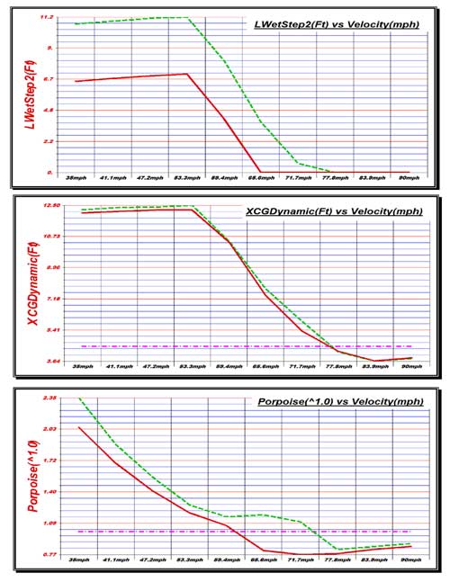
'Steps Performance
Analysis' including step wetted length, dynamic stability, and
porpoise analysis graphs [excerpt TBDP/VBDP, comparison of two alternative
step designs; 3 of graphs] |
Step Height and
Step Angle
A properly designed step can help maintain a
constant trim angle (WAngle), reducing cyclic changing trim angles under
operating conditions. Step Height and Step Length set the Step Angle, for
each step design. A designer can design the step height and step
angle to optimize the planing trim angle of the planing surface(s).
Step Height that is too low can sacrifice potential efficiency of the
step, and in some cases, can even cause additional drag with degraded
performance. A step
height that is too large can impose a step angle that is too high, causing
additional drag and, more importantly, resulting in very low hull trim
angles (even WAngle=0), exposing other surfaces to increased wetting and
extra drag under many conditions. Step height should be considered so that
step angle does not result in very low operating WAngles. A high Step
Angle (Step Height) can generate higher lift resulting in very low Trim
Angle (WAngle=0), which may cause lack of responsive trim control (you
can't trim down).
A reasonable guideline
is a step angle of less than 1/2 of optimum trim angle (example, if
optimum trim angle = 4 degrees, then max step angle could be set to less
than 2 degrees).
TBDP©/VBDP©
performance Reports provide analysis of step design, reporting for Optimum
Step Height(s) and Optimum Step Angle(s), and recommendations for Step
location, step height and step angles, as well as leading planing surface
design (forward of step surfaces).
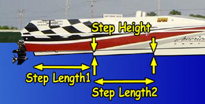
Multiple Steps
There are additional challenges with multiple steps.
1) If the steps
are located too close to each other, the water attaching to the second
step is "contaminated" by aerated low-density water from the first step,
so the aft step does not produce the high lift forces desired.
2)
Where do we locate the center of weight (LCofG) so that the weight is
balanced across the steps? Remember, the running trim angle can change
throughout the speed range and this makes a huge difference in the
lift-force distribution on your steps. It takes only a small change in
the relative locations of the CofG to change your boat from a stable,
efficient boat to one that porpoises at several velocities.
[TBDP©/VBDP©
performance design software helps to optimize step design and
placement, and provides performance analysis of any hull with or without
steps.].
|


 about Jim Russell