|
|
|
 |
Aerodynamic and Hydrodynamic Performance |
| Performance Boat design and setup secrets for Recreational tunnels, Offshore Cats, Racing tunnels, Fishing/Utility hulls, Vee and Vee-Pad Hulls, Bass Boats | |
| Home New About Us Technical Articles TBPNews Archives FREE Downloads Research Contact Us | |
|
Testimonials
Reviews
Join TBPNews
Advertise
Search
Buy Now
|
|
|
|
|
| AR© develops Multi-Engine Interference Drag | ||
| Get complete article by email request: | Share: | |
|
ADVANTAGE |
||
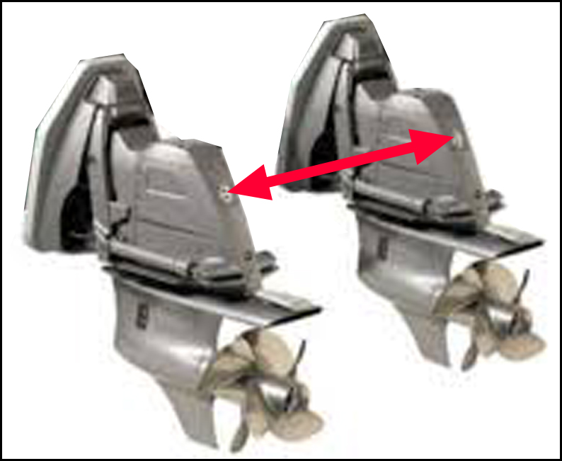 Figure 1 - Multi-Engine installations have an Optimum spacing between Drives/Lower Units
VBDP V8, Lower Unit design" Performance Analysis video |
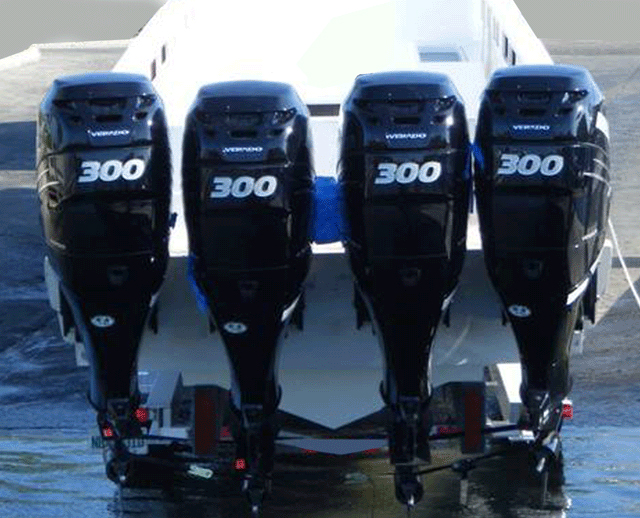
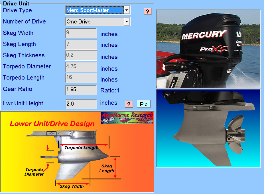
TBDP©/VBDP© Drive Unit Drag Analysis calculates drag and coefficients for ANY engine/drive configuration, including 'Multi-Engine Interference Drag' throughout the entire operating velocity range.
AR® has developed complex algorithms that calculate hydrodynamic drag of the outboard lower unit or I/O outdrive design & configuration. TBDP©/VBDP© accounts for multi-engine setups of 2, 3, 4 or 5 engines/drive units. There are several contributing drag components (see below) that determine the overall drag of the lower unit. (See more details "Drive Unit Drag Analysis")
With Multi-Engine installations the
engine-spacing setup can influence drive/lower unit hydrodynamic drag. This
can be important to overall performance, particularly at higher velocities.
When engines/drives are located in close proximity, there is a flow
interference between adjacent drive components, that results in an
ADDITIONAL hydrodynamic drag, called 'Interference Drag'.
Interference Drag - Research has shown that interference drag occurs when lower units of
multi-engine (outboard or sterndrive) installations are located in close
proximity to each other. As lower units are closer together,
interference drag can become significant. AR®
has developed analysis
techniques for calculating 'multi-engine interference drag' and TBDP©/VBDP© accounts for this drag based on
lower unit configuration and multi-unit spacing.
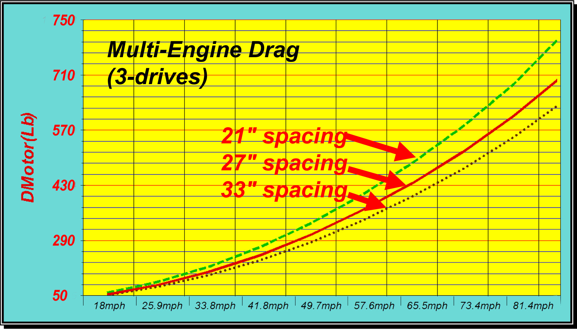
Hydrodynamic drag of drive/lower units is increased
when drives/lower units are located in close-proximity. The optimum
spacing between engines or lower units is a function of: How It Works: For the example hull setup, the increased hydrodynamic drag of close proximity engine placement can add +2% of lower unit drag (per engine pair) - so, +4% for 3 engines, compared to optimum spacing. Very tight engine placement can increase this even more +3%/+6%. Opitimized multi-engine placement can be an important performance improvement, if the design/setup can position engines at (or more) than optimum spacing. [Note: (TBDP©/VBDP© software does complete drive/lower unit drag analysis, including Torpedo drag, Skeg drag, Leg drag, Induced Drag, Spray drag, Interference drag; Also calculates torpedo lift, torpedo induced drag, torpedo resolved lift correction. Also calculates optimum multi-engine spacing to minimize interference drag.]
|
|
|
||
|
The Drive Unit hydrodynamic drag results are
presented in standard
TBDP©
and
VBDP©
output and in graphic analysis format.
TBDP©/VBDP© makes it easy to see the performance and stability improvements that are achieved by design modifications and/or setup changes. |
||
|
[more about AR's research more about AR's publications and technical articles/papers] |
||
